
Know that this is certainly going to be a more technical post, but should still be interesting for people that are curious about how games are created, even with little to no knowledge on the subject.
This post is going to focus on my delves into the depths that is mesh generation for a 3D terrain, note that I am not going into much details outside the actual mesh generation, there is certainly a lot that can be said about Normals, Shader and other minutia, but not today.
To be completely fair, I started this whole affair knowing pretty much nothing about this myself, sure I know how voxels work and have done a minecraft-esque implementation of a voxel mesh myself, but that was following tutorials and it’s concept is way simpler than actually creating a more organic looking terrain.
If you want to create a terrain in any type of game or simulation, you will need to figure out how to turn the terrain data into polygons or: How do we turn numbers into a landscape?
Sure we can just fire up Blender and model some nice terrain there, we can even texture it and give it some advanced details. But we want to be able to change the terrain at runtime, i.e. dig into the ground or have an explosion create a crater, so just modelling it is out of the question.
By far the easiest and quickest solution would be a heightmap based terrain.
Such terrains are generated from two dimensional information, this is usually done with either a perlin noise, often layered, or a handcrafted greyscale texture like on the image shown.
If we take the shown image as an example, every dark pixel would be a lower part of the terrain with black being the absolute bottom, usually sea floor, while the brighter pixel will end up as the higher parts with the brightest pixels being the mountain peaks.
While this can result in a very decent looking terrain that is very lightweight, it’s not without it’s caveats.
Heightmap based terrains have quite some downsides, you can’t have overhangs or caves unless you remove parts of the mesh which leaves an ugly hole that is hard to mask. There is also a substantial loss of detail on vertical parts of the terrain like cliffs or steep mountains.


So we collectively decided that we did not want to use a mere heightmap for our game since we want to have interesting caves and mines and want to allow more sophisticated terraforming since heightmaps would limit us to raising and lowering the terrain due to it’s two dimensional nature.

There is very few other ways of handling terrain, the most popular being “Voxels”.
Voxels or volumetric (3D) pixels are building blocks of a lot of games, especially sandbox games, from No Man’s Sky, Space Engineers, Minecraft and many more, basically every time you find yourself in a game where you can freely dig or manipulate the terrain it’s very likely some form of voxels.
But Voxels are far harder to handle and have a lot more complexity, which in turn impacts calculations/render times and network load. But we wouldn’t have gone for voxels if we weren’t sure we really needed them, especially considering this isn’t exactly an easy or small topic for any game, it’s quite literally the foundation of the game’s world.
But just knowing that we want or need to use Voxels is not enough so I began researching on the topic, to see what others are doing with voxels and what we can do to avoid the blocky look as that would not quite fit with the semi-realistic style we want to aim for.
While we want to utilize Voxels to create an interesting looking terrain with caves, overhangs and nice cliffs, they have much more potential than that. It’s really impressive to see that people are able to have voxels fully dynamic and physically interacting with everything and even volumetric smoke using Voxels.
Suffice to say there is lots that can be achieved with Voxels and while I don’t think I will be experimenting with Voxels outside of the terrain it’s still going to be a very important part and hopefully merges well with the rest of the gameplay we have planned.
The first step is to create a three dimensional world filled with voxels according to some form of noise.

Now there is one question that remains, how do we create a terrain from this that looks realistic and organic?
Wikipedia: “An isosurface is a three-dimensional analog of an isoline. It is a surface that represents points of a constant value (e.g. pressure, temperature, velocity, density) within a volume of space; in other words, it is a level set of a continuous function whose domain is 3D-space.“
A bit convoluted I admit, but an Isosurface describes the surface of specific values in a three dimensional area – in our case this would be our voxels. For example to describe the shape or rather surface of clouds, depending – among other things – on moisture/density (determining the “edge” of the cloud). Another use case are medical scans, like CT scan, which produces layers of two dimensional data that represent human tissue, this can be represented three dimensionally using Isosurfaces, which is actually where a lot of the research leads to, because really knowing how a fractured bone looks or some damaged organs can help finding the correct treatment and understanding these types of injuries tremendously.
But it can be a little difficult to understand how Isosurfaces are meant to work without visual aid, so here are some examples:


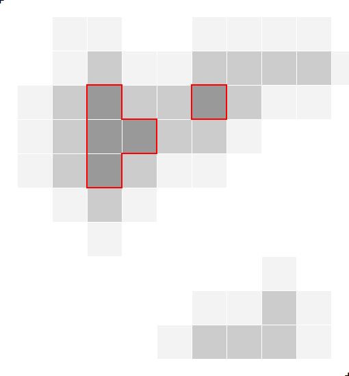
Take this 10 by 10 grid of values (fig. 1), represented by shades of grey (NO, just don’t.)
Depending on what you are looking for you will need to determine the threshold value.
This can be rather arbitrary for most cases, but it depends what you are trying to create a surface for and what your data looks like, ours are just random greyscale values from 0 to 1.
Now the threshold is used to determine at which point our data or noise is to be interpreted as part of the object or not. Only once we know which voxels are “solid” can we continue and actually create a surface for it.
If we set the threshold too low, we end up with too much surface and might lose details, since it will take more values into account. (fig. 2)
On the other hand, if we overtune the threshold, we might end up with the opposite: too little left, leaving the remaining surface fractured or even torn apart. (fig. 3)
Generally I did not have to worry about the threshold, so it is quite arbitrary at some value ~0.7, but really depends on the type of data and the way it is generated.
As a sidenote: Minecraft does this too, it determines what blocks are actual “solid” terrain like Stone, Dirt and Ore – and the rest is just considered to be “air”.
Once we are certain what blocks are actual part of the terrain, we can move on and generate the surface and preferably smooth it to get rid of terracing artefacts and jagged edges where the original data does not intend such.
There are a couple of ways of going about it, but I want to keep things at least somewhat simple and it would be nice to retain the ability of looping through every block so here are our best candidates:
Note that these are only some options that I looked into and that were halfway decently explained on the internet.
Needless to say, as the title is a bit of a spoiler, we picked Surface Nets, but I will briefly go over all three of them.
The first I heard about Marching Cubes and really the catalyst that led me down this rabbit hole of surface constructing, was this video on it:
The general idea is to march (loop) through every position of the world and depending on surrounding blocks, where our threshold and noise comes into play, construct the mesh according to (usually) predetermined shapes via a lookup.
This has the tremendous advantage of having barely no calculations for the mesh construction, as you are just checking neighboring blocks and lookup the corresponding arrangement of vertices and faces to put in. Though the logic on that can get a bit headache inducing, so I won’t cover that here.
Marchin Tetrahedra works similarly but the resulting mesh will end up having quite a lot more vertices and faces, which can be nice, but it also is a lot less GPU friendly, due to it’s massively more complex mesh.
But Marching Cubes itself (Marching Tetrahedra certainly not) is pretty lightweight in terms of the result, the amount of faces and vertices created is pretty low, further increasing the efficiency potential of the algorithm.
But if Marching Cubes is so good how come we did not pick it over Surface Nets? To be completely honest: Looks. Granted it sounds superficial, but if we weren’t bothered with looks we might as well just use a heightmap and call it a day.
Creating a voxel terrain from cubes is actually pretty easy with tons of guides and tutorials out there. Ideally we could just use that and just smooth it a bit; This is where Surface Nets comes into play, it takes a regular cube-like voxel world and just: Smoothes all corners iteratively.
This sounds really great and easy to implement, but it’s not quite as easy…
For a regular Minecraft-like voxel world in all its cube-y glory you loop through all positions of the world and generate a cube whereever you encounter a so-called “solid” voxel that has non-solid voxels adjacent to it, plus points for only creating the faces and their vertices that can be seen.
The only thing left to do is move the vertices – the corners of each cube – toward some smoother position as much or as little as we like and pat ourselves on the back, but how do we move the vertices and how do we get this “smooth position”?
Instead of focussing on one voxel at a time, we need to shift gears and only focus one intersection – one vertex – at a time. First we need to define the Surface Net:
We loop through every position.
We check the neighboring voxels but only in positive direction (to avoid duplicate entries)
If all neighbors and the current voxel are the same, they are either ALL inside or ALL outside of the terrain, so skip to the next and repeat.
Should any of the surrounding voxels differ from the currently observed we add the current voxel to the list as it is considered a surface (net) voxel.
After we have looped through every voxel we have our complete list of vertices. We also need a list of all neighbors for each vertex.
// Start at x, y and z = -1 to account for the fact
// that we only check neighbors and create mesh in positive direction
for (int x = -1; x < world.worldSize; x++)
{
    for (int y = -1; y < world.worldSize; y++)
    {
        for (int z = -1; z < world.worldSize; z++)
        {
            // check 8 neighboring voxels
            int sum = 0;
            for (int dx = x; dx <= x + 1; dx++)
            {
                for (int dy = y; dy <= y + 1; dy++)
                {
                    for (int dz = z; dz <= z + 1; dz++)
                    {
                        // If a voxel exists, add one to our (check-)sum
                        if (voxels[new Vector3Int(dx, dy, dz)])
                            sum++;
                    }
                }
            }

            // The sum is only 0 or 8 if all checked blocks are the same
            if (sum % 8 != 0)
            {
                // Surface Cube found, add Vertex
                surfaceNet.Add(new Vector3Int(x, y, z), new Vector3(x, y, z));
            }
        }
    }
}
The resulting list of vertices describes our terrain surface:
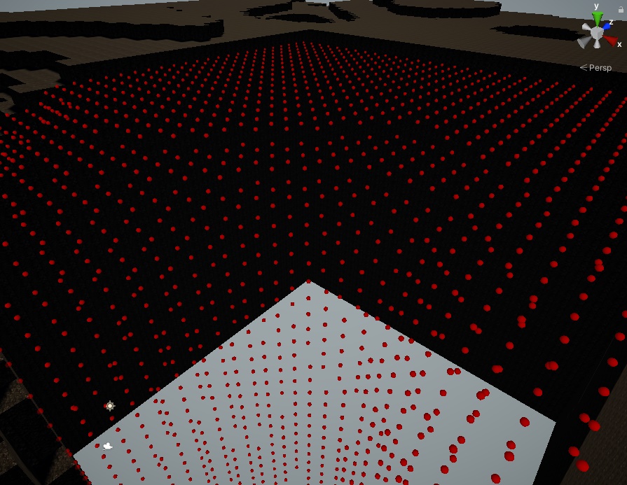
Progress!
Now we can loop through every one of those vertices (substantially less than every possible position of the world) and apply some… math.
The “Naive” approach is to simply average all adjacent vertices current position and move the current vertex toward that position. So basically just linear interpolating between those points. Then repeat the process with the new positions as often as you like and voilà:


… eh?
Is it just me or did it shrink? Yes, yes it did. And for good reason!
Unless we have infinite time and an infinite terrain, the average position of the voxels will converge in the center of the mesh. This effect is stronger the closer a voxel is to the border and the more iterations we do.
And there are more problems. Firstly we had cases where the mesh would fold in on itself after too many iterations and the second was a problem where the terrain was turning too smooth after the first few iterations.
The first problem is a bit tricky, but Sarah F. Frisken Gibson already had this problem back in 1999 and described a solution to it in her paper:
…to remain faithful to the original segmentation, a constraint is applied that keeps each node inside its original surface cube…
So that is exactly what we will be doing: restricting a vertex’s position to be always inside it’s origin “cube”.
The latter issue can be solved surprisingly easy, just by making sure the effect of each iteration is always a little bit weaker than the last. This way we can have a handful of iterations without the terrain getting too smooth at places where it really shouldn’t.
But I won’t go into detail on these problems and solutions because that would easily double or triple this already long post.
Now instead of just interpolating every corner (vertex) position with one another, say we could mathemagically calculate a relation table, as a matrix, for every vertex in the whole system / terrain.
This means that we know all forces every vertex is subjected to (pushing and pulling from their neighbors). With this we can take the current, future and previous positions into account for an explicit calculation. So it’s similar to the original approach where we adjusted positions each iteration, only that we now take into account the final “optimal” position each vertex should try to aim for, as well as the previous position of that vertex.
Alternatively we can use an implicit approach that reverses our logic; It starts from the future position of each vertex and tells us exactly where we should move our vertices to, this depends on a few constants that we can control to adjust the final result to our liking.
I am obviously heavily simplifying here but for anyone interested, this is the formula used to calculate the explicit position:
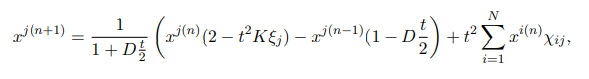
While the implicit method is very precise and potentially the most accurate in terms of retaining features of the original terrain, it is also the most complex mathematically speaking and involves a lot of calculations with matrices.
This results in the worst performance out of all methods so far (though we haven’t done a terribly well job optimizing it). It is important to mention that all the heavy lifting is only done once at the beginning, to calculate the relation matrix and some inverse matrices that are needed to get the result.
Since we want to be able to interact and edit the terrain at runtime – i.e. digging, mining and so on – we opted to favor the explicit method, at least out of these two, even if it is a bit less stable.
I should probably go into what “less stable” means.
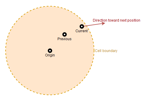
This is a visualization of what the explicit method does (simplified). Now we need to make sure that the position is never outside the boundaries. To achieve this, we may nudge the position back in the opposite direction, this can lead to overcorrecting and produces oscillation of the vertex position where we constantly overshoot the boundary and then move the vertex back too much, resulting in a very spiky terrain:

For now we have fixed it pretty simple with some spring constant to counteract an overshoot and a dampening constant that makes sure we don’t overdo that either. But even with those two constants it’s still a bit volatile sometimes (when we change any of the settings), hence: unstable.
And while I am extremely impressed that all of this matrix stuff actually works, since I never used anything as math heavy like this in calculations before, it hasn’t exactly been working right away…

But after we sorted out some bugs, simplified the source code and fine tuned the constants for the oscillations, the results of the explicit method were pretty satisfying as well.
All the calculations and formulas have been created by Paul, there is a file with the formulas and explanations (in german) at the end of this post.
When we take away the implicit matrix based method we end up with two ways of doing basically the same thing:
I added logs for time for both the smoothing and the generation of the surface net prior to it (to reduce bias).

The image above with a chunk size of 32³ had the following times:
Needless to say we dropped the implicit method, while it wasn’t anywhere near full optimization, it was so far worse than the rest that further work would have been a bit pointless for our use case.
Explicit actually got improved quite a bit from it’s initial >500ms and there still seems some room for improvement, especially with the option to have some it pre-calculated and hard code it in, but we leave that for another time.
It’s also important to note that while the linear interpolation yielded it’s results the fastest, it’s also scaling linearly with every iteration much like the explicit method does, but the bulk of calculation of the explicit method is done before the iterative part so more iterations will put the explicit method into a better ratio when we do lots of iterations, but from what we tested just 3-5 iterations was already enough to yield good results.
It was also interesting to see how well each method would stack up with something less smooth.

Aside from the aforementioned issue with the Surface Net “contracting” I also still have to find a way to stitch chunks together without making an obvious seam as well as thinking about an LOD system so terrain can be viewed from afar without melting the hardware.

But most of this is not as complicated and more a matter of making it look right, it’s also nothing exclusive to Surface Nets, so I am not too worried about solving that, yet.
Also I know that the performance would get quite the boost if I switched the smoothing calculations to run on multiple threads, but that’s another topic I really have to understand before implementing any of it, for now I am satisfied with the performance and keep multithreading on the back of my head for when I inevitably need to improve the performance.

That’s pretty much it, I will keep sharing progress on this as long as it’s interesting enough to write about. Since this is an inheritely complicated topic and I want to make this understandable, to help people like me who are trying to get behind stuff like this in the future, let me know if you feel something is unclear or not specific enough. I am also still uncertain if the length of this post is good or if I should split it into multiple posts next time, any constructive feedback is appreciated here as well.
Cheers!
Force.pdf – A breakdown of the calculations used in the explicit and implicit method, in german by Paul T.